Back to top: Errors
Introduction
The general approach to errors is described in the identification of errors and accidents section of the Mozan sitewide book. The approach is to preserve each recorded data element, based on observation or measurement. Some of the data is occasionally incomplete, conflictual, or incorrect. We specifically address these factors when they significantly impact a constituent. However, for the most part, errors are small and have little cumulative effect. We discuss the recurring problems below for clarity.
Back to top: Errors
The excavation forms are filled by the unit team. The fact that these forms are handled by different people, creates some issues with spelling (most members are not native English speakers), besides the difficulty in reading hand writings.
Back to top: Errors
Documentation
The team follows a strict and thorough documentation system. However, when working on the data from an excavation unit after the passing of some time, a need for more general information than the ones that were considered during the excavation, arises. This only become apparent when working on the entire narrative of the unit.
J4 lacks general views that puts into perspective its relationship with the adjacent units like J6 and J2, which brings more clarity to its position and role within the entire Temple Terrace and Temple Complex.
Back to top: Errors
Vector drawings of sections
The vector rendering of sections (usually the north and east sections of each loci are drawn), contained many errors. The listing of these errors is not meant in any way as a criticism to the colleagues and students who worked hard on them, as I know personally how difficult it is to keep track of large amount of daily data, in a short period of time. It is however meant as a way to draw attention to the fact that retrieving an information after the excavation, can be hard and very time consuming. Below are the main issues with the drawings and the vector format of these drawings:
- the lack of uniformity in the placement of the information on the drawing, resulted in some chaotic looking drawings, and the negligence to register some important information, such as the elevation of the nail.
- in many drawings, the hand written information is very difficult to read, meaning that it is lost in some cases.
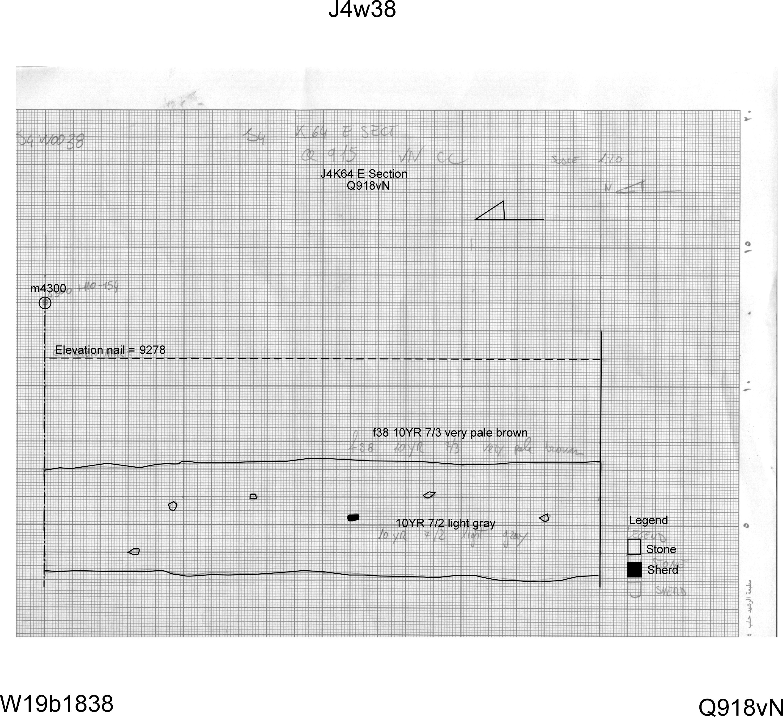
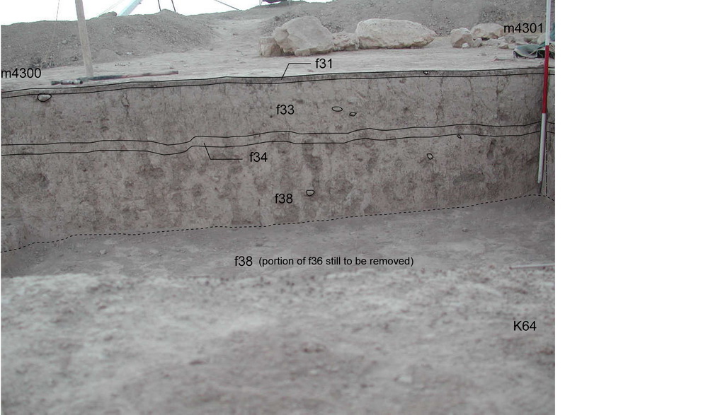
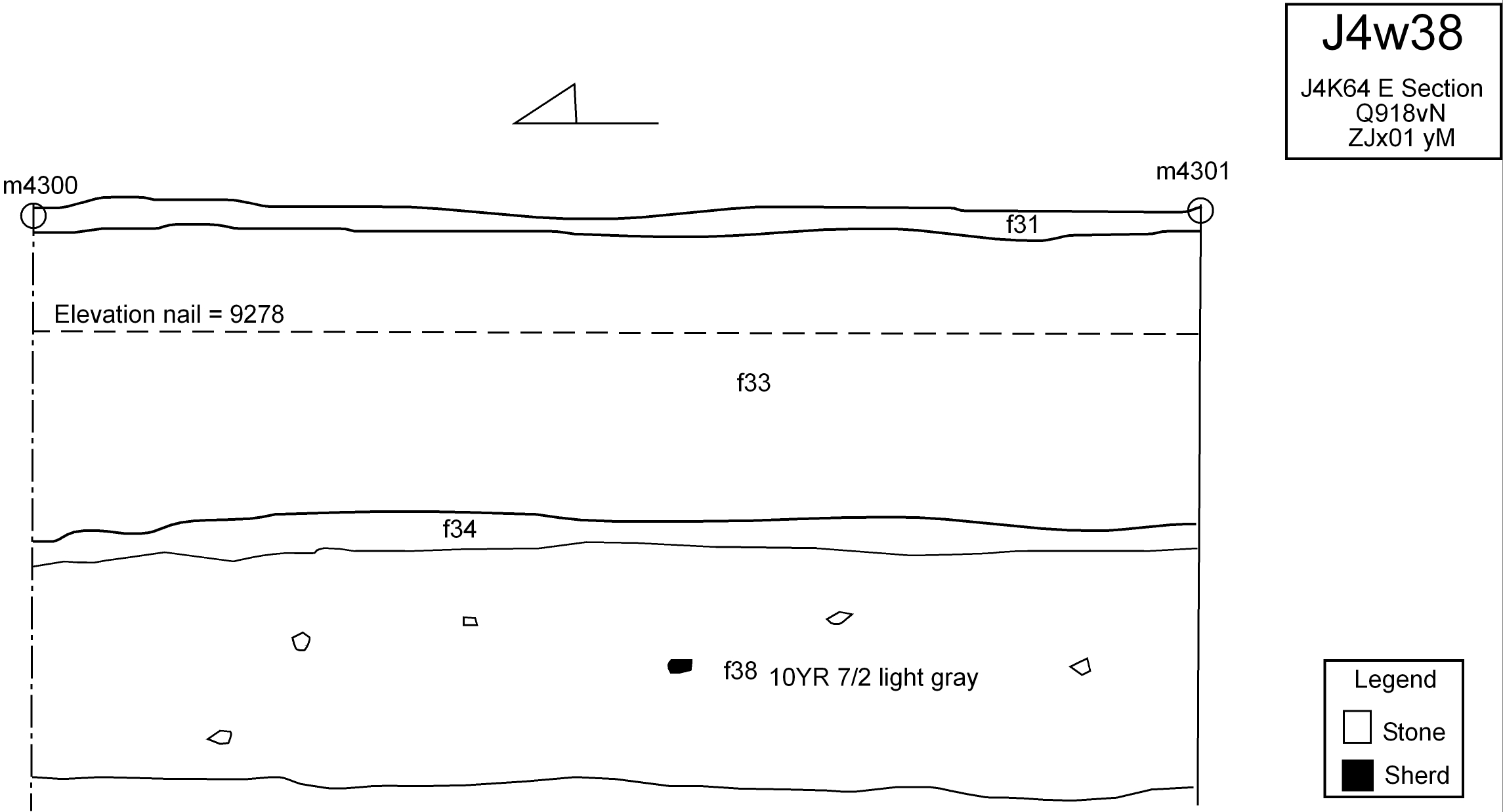
- some pencil and vector drawings were not complete, where only one feature in illustrated, omitting the many other features shown in the photo template of the section (J4w38 as an example). The photo below shows the section as it was drawn, the template photo, and the way it was adjusted to match the photo template.
- in some cases, the photo of the drawn section is missing, making the retrieval of the missing information, such as feature numbers (which was not registered anywhere), very difficult.
- when there is no indication of the marker on the drawing, and the nail elevation was omitted, resulting to other methods to complete the drawing became indispensable. An example is J4w0023 . Being the eastern section of k72 is the only information on the drawing. After looking at the views of k72, and finding the photo of the section, it was possible to retrieve the feature numbers.
The other problem with this section drawing is that it represented only one feature, where there should have been two features. The second feature was added based on the photo template of the section J4t0051. However, the template was made using the photo without the string, therefore, the added feature line on the vector drawing is not very accurate.
The final step is figuring out the elevation of the nail which was not registered. The photo and the drawing do not specify a marker from which this elevation can be calculated. Therefore, it was calculated based on the top elevation of the upper feature (taken from the feature page) minus the centimeters down to the string, which was calculated based on the drawing scale. Needless to say, this time-consuming process could have been avoided by making sure to register all the information on the pencil drawing in the field.
It is important to know that in these cases, a note is included in the vector drawing, which clearly states the process of information retrieval, with the initials of the person who worked on it.
Section drawings are a powerful tool in the reconstruction of the stratigraphic deposition of the area, and making the best use out of them, entails having an accurate registration of elevations, markers and feature numbers.
Back to top: Errors
Feature assignment
J4 contains many accumulation layers, and many isolated stones resting on accumulation layers. The natural accumulation on which the stones rested, were given a feature number and termed pedestal. In reality, these are not pedestals that were intentionally created as pillars of soil for these stone, but they were rather excavated this way because the team was trying to understand the nature of these stones and find alignment before removing them, hence excavating around them and giving these “pedestals” a different number.
While this is not an error, because there is a description that clarifies the nature of these features, it does add complexity to the general stratigraphic situation and creates more “types of contacts” with other features, which is not necessary and to be avoided in future excavations.
Back to top: Errors
Phases and strata assignment
The phases in J4 were assigned using the MZA frame. This is not compatible with the other units of the Plaza and Temple Terrace area which uses the JPD stratigraphic chart.
This is not an error but a compatibility issue. Therefore, the following chart provides the corresponding phases in the various stratigraphic assignment charts.
Back to top: Errors
Markers
The marker issue is of great importance, as they can help retrieve valuable information. The J4 body of data did not contain a file designated to the listing of all the marker delimits the excavation area and the loci. A sketch of the loci plan did list some of the markers for the loci and baulks, but not all.
Retrieving the information through the photo templates, which specify the markers delimits the loci in the photo was effective to some extent, however, it did not result in the retrieval of all markers.
An attempt to retrieve this information from the plot files was made. The following problems arose:
1- The plot files needs AutoCAD or a similar software to open these types of files.
2- What was assumed to be a plot file for J4, turned out to be a plot file for a different excavation unit (J1).
3- Trying to retrieve the information from the marker file on the main server is extremely difficult, as the file label does not provide information about the location of the marker, and inspecting the content of all the files one by one is very time consuming.
Back to top: Errors
Relays
Relays r74, r139, r161, and r162 are missing.
r74 was assigned to f101.2. f101 is an isolated stone, and f101.1 is also an isolated stone considered together with f101. There is no f101.2 to which r74 was belongs, so it was canceled.
The reason behind the other missing 4 relays is unknown.
Back to top: Errors
Templates
Template number 2 was removed, because it was a corrupt duplicate file of template t3. It was decided to make a note about this here instead of renaming all the subsequent templates to accommodate this error.
The same goes for t73a, which was deleted, as there are two other templates that reflect the same situation (t73, t73a)
Back to top: Errors